The Halo Machine
SYNOPSIS
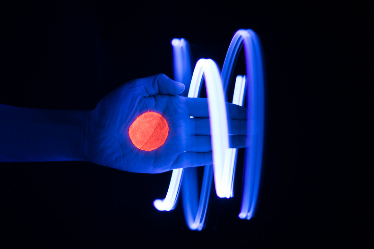
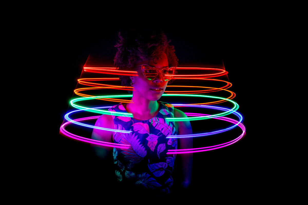
The Halo Machine is a device of my own design that allows me to control the spin ( rotational speed ), state ( on/off & intensity ), and position ( x, y coordinates ) of multiple LED lights during a single-exposure photograph. So far all shots have been captured in a light controlled studio using a Sony a7rii mirrorless camera with a 35mm lens. Further, depending upon spin, shutter speeds have been typically between 0.5 - 1.6 seconds. In this article I explain both the impetus for the idea of The Halo Machine as well as how I went about its construction.

IMPETUS
The idea of The Halo Machine evolved from my early experimentations with homemade devices for light painting. Starting in 2016 with a simple dog collar light tied to the end of a string, these contraptions slowly progressed in terms of their complexity - each providing me with different forms of control over light. However, their mechanical limitations are what pushed me to extrapolate how to take it to the next level. See, for me the art in all of this is in figuring out how to orchestrate the presentation of light to the camera during a long, single exposure shot to produce surreal images that make a viewer wonder “How did he do that?”. Unfortunately, what I’ve found is most people just assume I’m using a design tool or Photoshop - not the case at all. But I digress… Anyways, I began devising plans for a far more complex device that would allow me to control the spin, state (on/off), and position of multiple LED lights simultaneously as they moved around a subject.
String Light | 2016


Graffiti Mallet | 2018


LED at the tip of the mallet wired to coin batteries at the base and a thumb switch.
Light Fork | 2018

V1 & V2 prototypes. LEDS in tips run by coin battery while the DC motor (which was eventually housed in a PVC pipe handle) run by independent 9v battery.
Pride Strand | 2019

Strip of LEDs wired in parallel with On/Off switch.
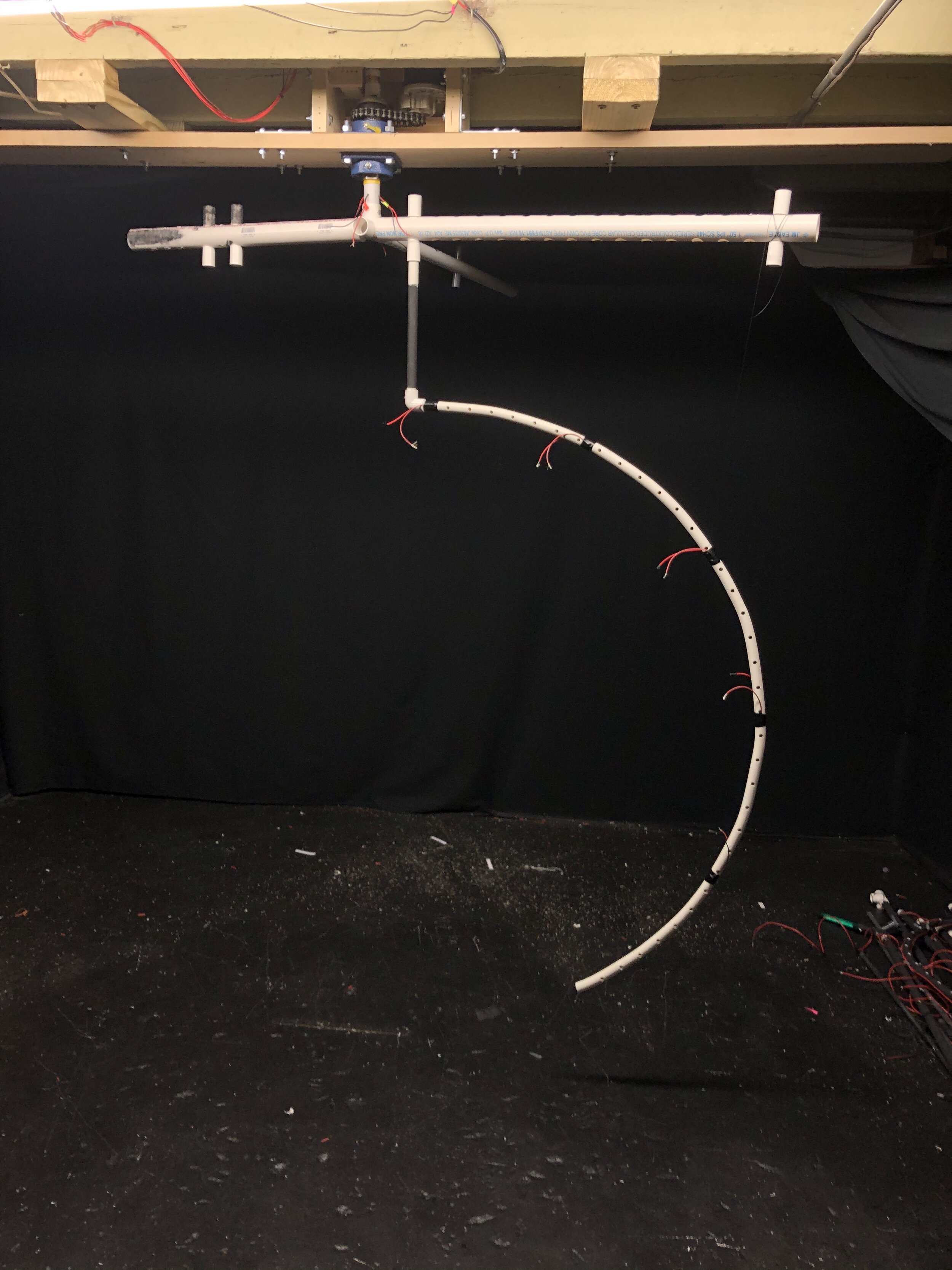
Halo Machine Prototype | 2019

CONSTRUCTION
The construction of the Halo Machine started in January of 2020. It’s been a process of trial and error and iterations are still taking place. Half the battle has been figuring out what to call the parts / mechanisms visualized in my head and then how to obtain them. Having that said, I think the best way to explain how I’ve gone about building the Halo Machine is to break it down by my approach to controlling the spin, state (on/off), and position of the LED lights that generated the images seen at the top of this page.
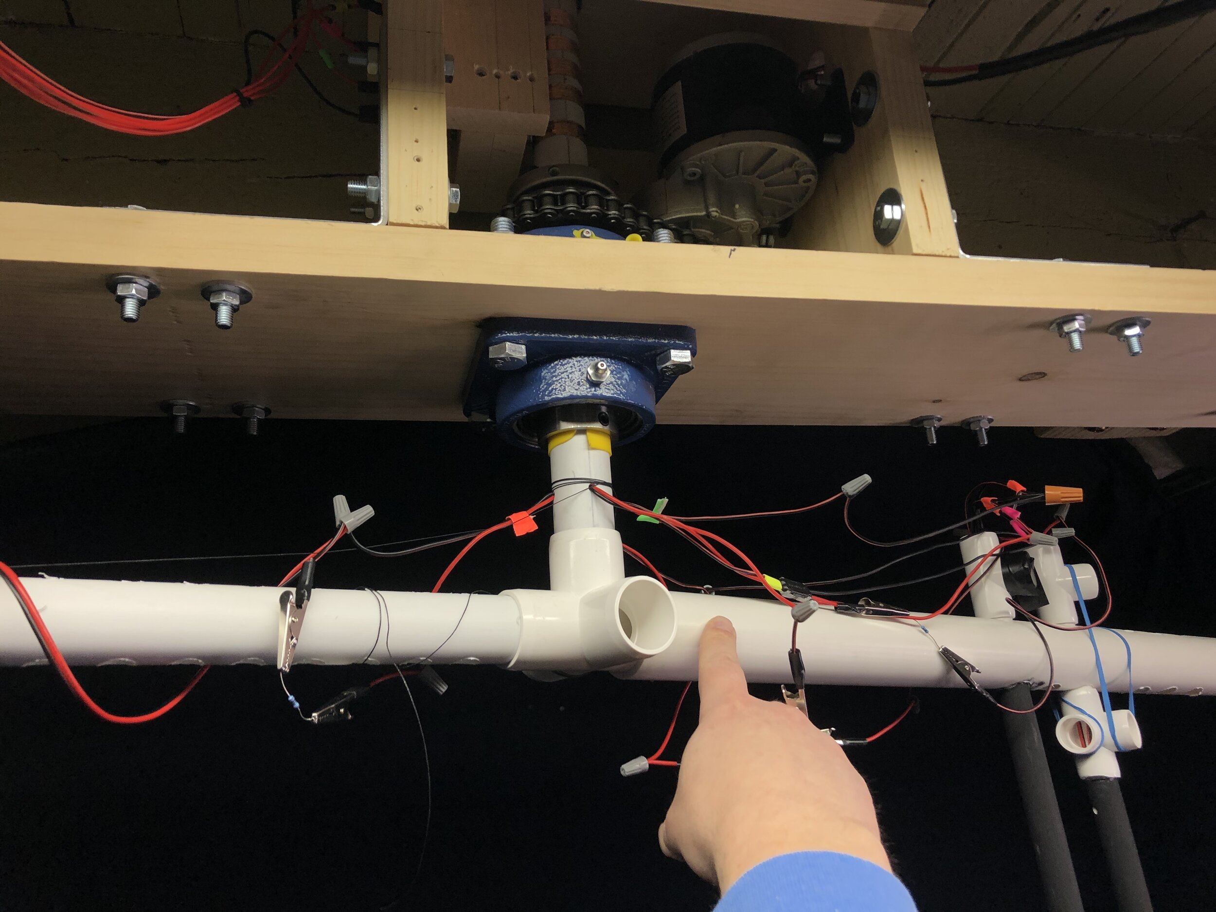
SpinTo control the spin of the lights, I used a 24v electric bike motor to power a chain-driven pulley system that spins a shaft made from 1” PVC pipe. Here, the shaft is held in place by a bearing mounted to the base board. To reduce the output RPM of the motor, I used a sprocket twice the diameter of the one on the motor ( 2:1 ) to cut the driving RPM in half. This created a more desirable range in speed ( so far most of the shots I’ve done have been at approximately 40-60 RPM ). To power the motor, I wired two 12v DC batters in serial ( not parallel ) as this makes the total voltage additive in nature ( 12v + 12v = 24v ). Further, I used a variable speed regulator to control the power delivered to the motor ( see video ).

The 1:2 ratio in sprocket diameter cuts the driving RPM in half. This creates a more desirable range in speed. So far. most of the shots I’ve done have been at a speed of ~40-60 RPM.
StateControlling the state of the lights ( on/off ) while spinning, took a bit more thought. Here, the problem was that the lights had to be part of a circuit - which would include a power source, a switch, and wires to connect everything. So how do I wire continuously spinning lights into a circuit without having the wires twisting and breaking after one rotation? To accomplish this, I created a lead box out of carriage bolts and springs that push up against copper bands around the shaft. The copper bands connect to wires inside the shaft that then carry the power down the spinning shaft and eventually to the LEDs. Though this was all one circuit ( drawing power from a single source ), I wired it to have four parallel channels - each with their own on/off switch. The idea was to be able to control the power to four individual spinning arms holding drop poles with LEDs.


Spin + State ( Housing )The motor, pulley system, shaft, and lead box were all squeezed together into a single housing unit. This involved a lot of trial and error in terms of measurement. Though imperceivable to the eye, there are slight variances in the position of the PVC pipe shaft as it spins - and both the chain-driven pulley system and the spring loaded leads operate best within a sweet spot of tension. Too much tension in the chain, it can place strain on the motor. Too little tension in the spring-loaded leads and they might break contact with the copper bands. Once I found a happy medium, I mounted the housing unit into the ceiling of my basement studio.

Spin + State ( Control )In order to operate the Halo Machine at a distance, I created a control panel out of an old plastic container. Each of the color-coded switches controls the power to one of the four channels in the circuit - which is powered by a 9v battery. I made the mistake of trying to use a 12v battery and smoked a few resistors in the process. The fifth switch is a master kill switch for the whole lighting circuit. The motor, however, runs on a different circuit which, as I mentioned before, is powered by two 12v batteries ( on the floor below ). Here, the button and dial in the middle of the panel control the power and speed of the motor respectively.

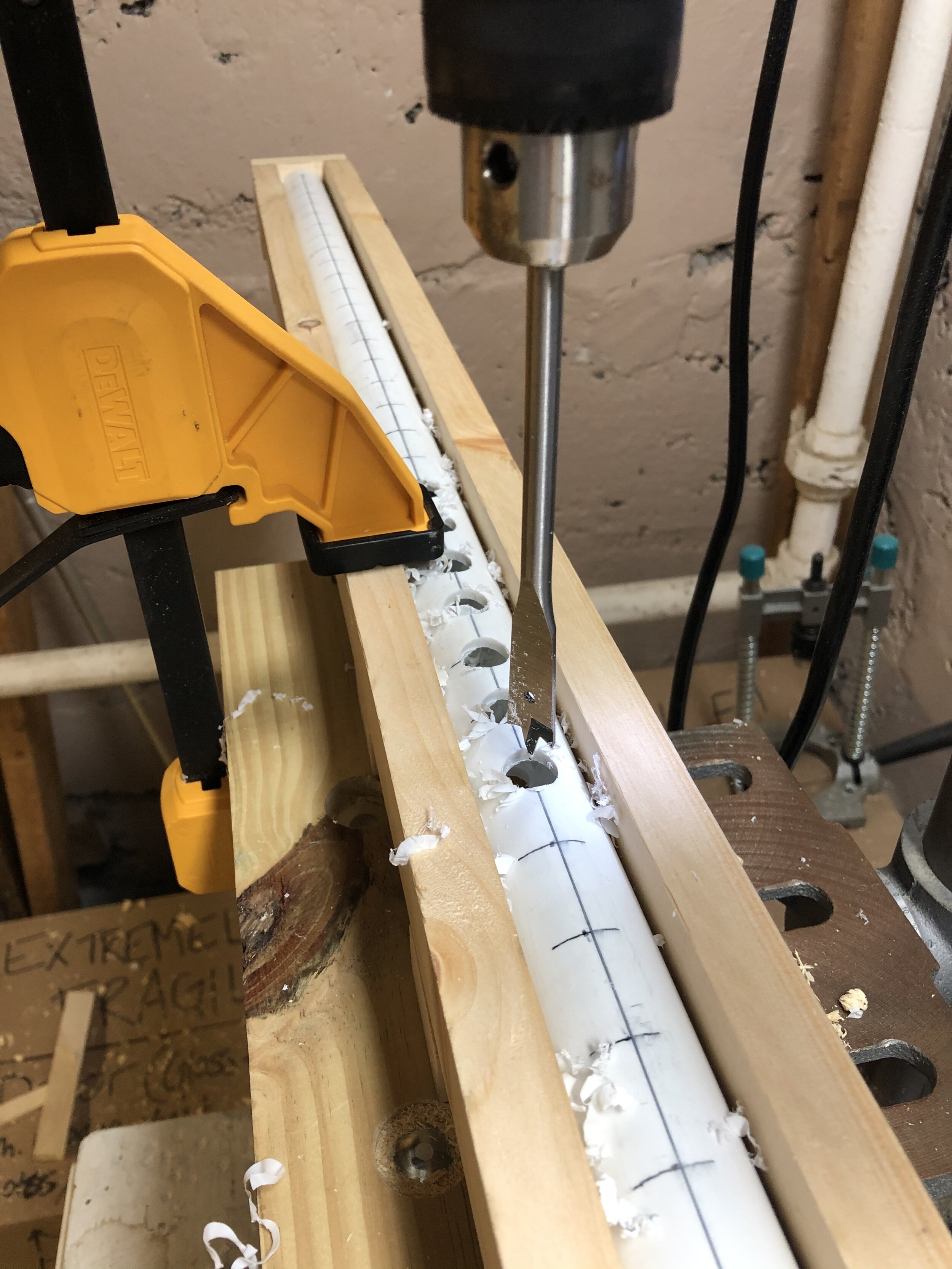
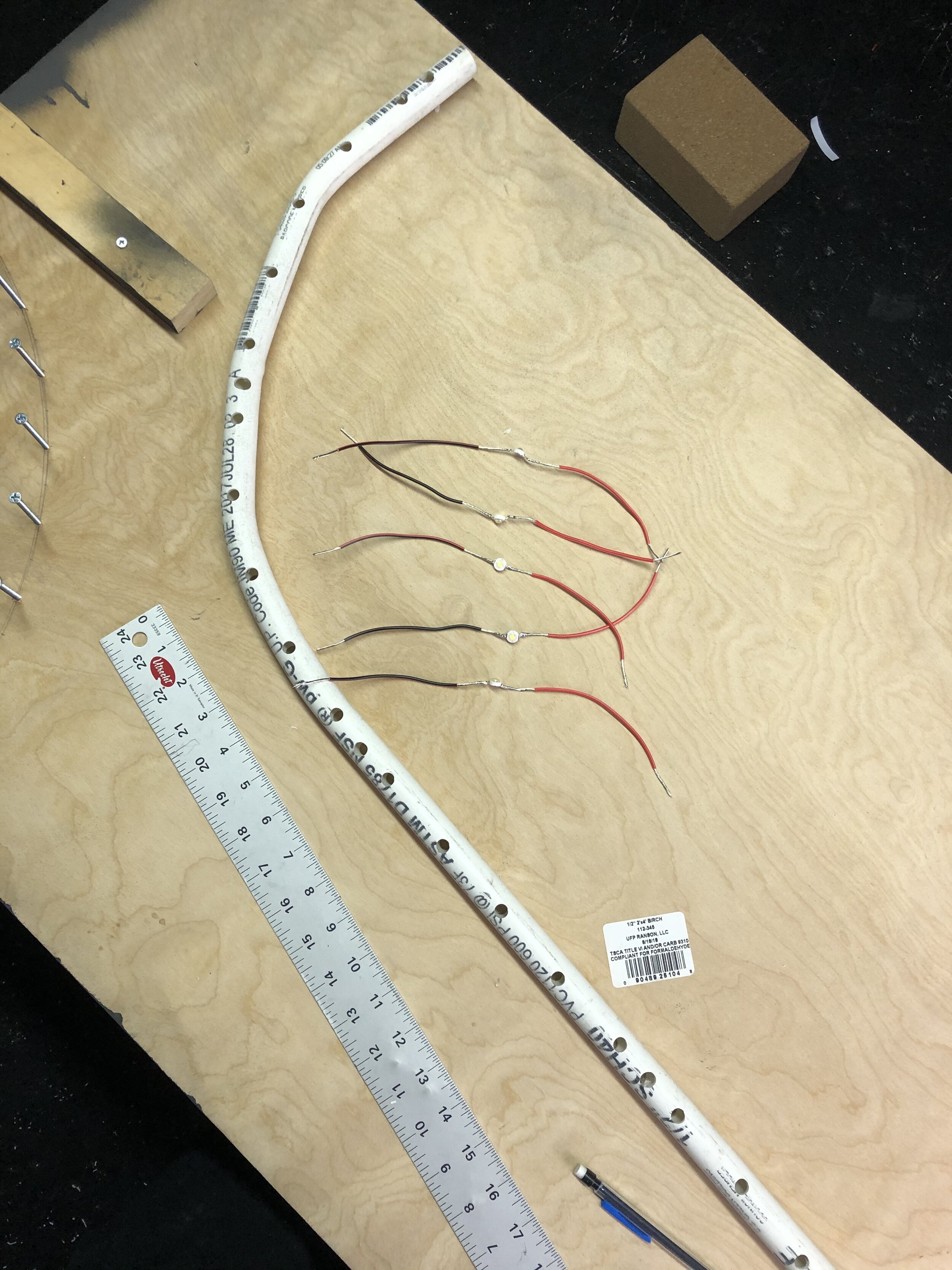
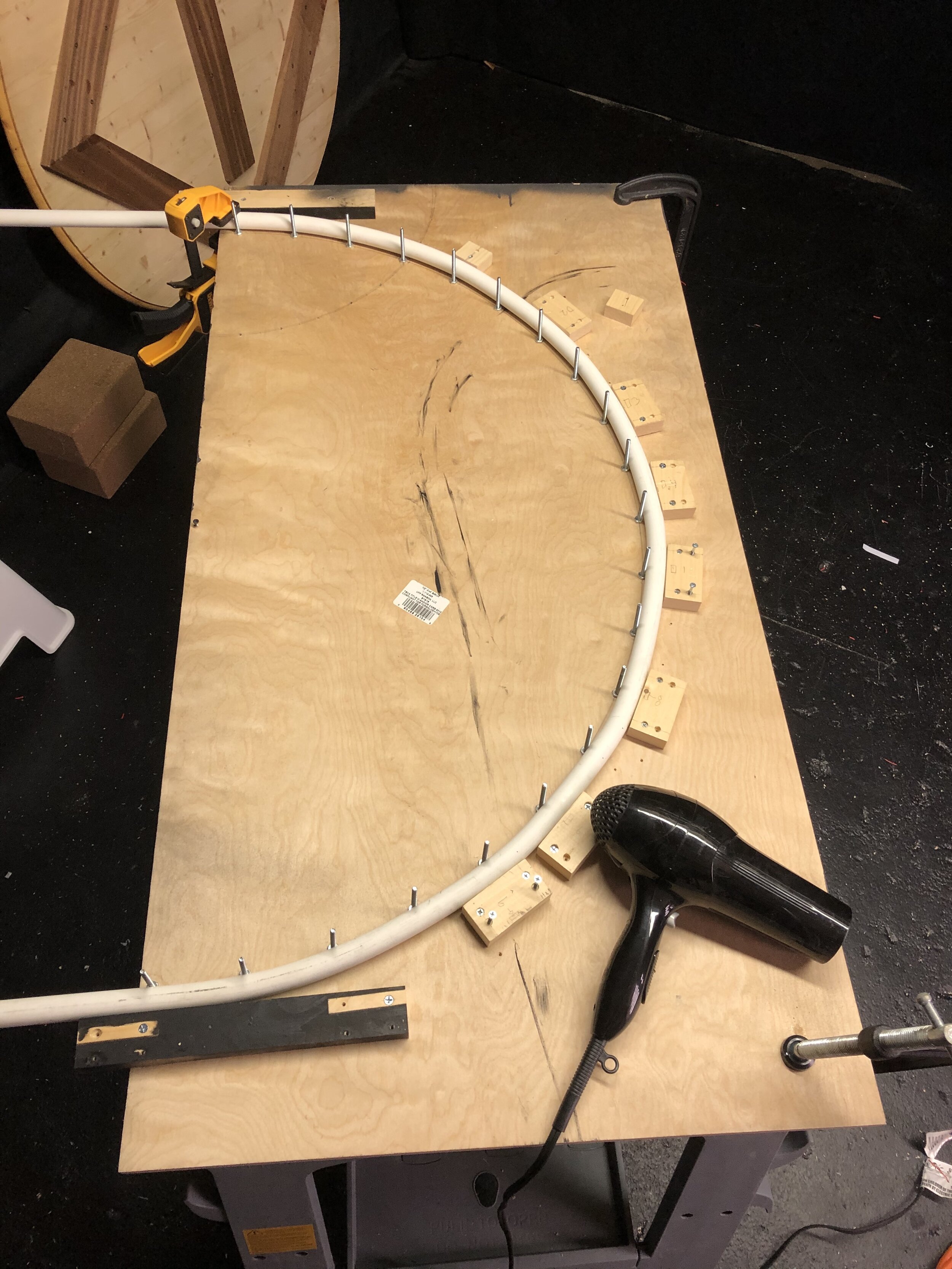
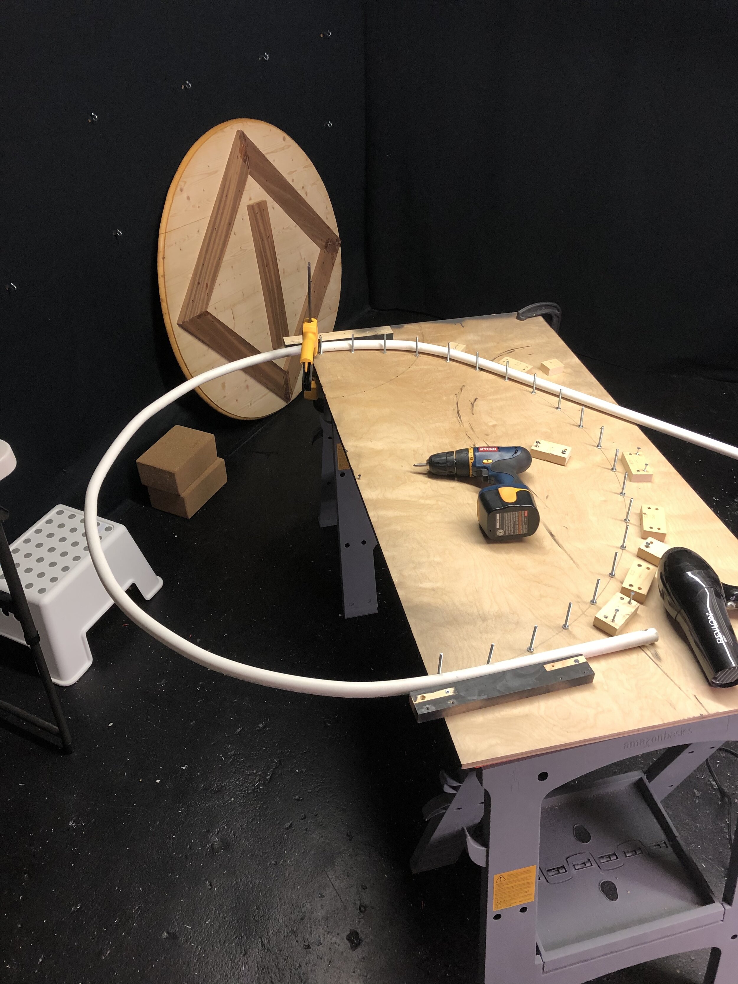
PositionIn order to control the position of the LED lights ( i.e. height and distance from center ) while spinning, I built - and am still building - a system of interchangeable arms, drop poles, and LED light housing units. For this I’ve been using PVC pipe as it is easy to customize and becomes quite malleable when subjected to heat.